Rough automatic draft, low quality: expect mistakes and awkward wording. It will be replaced by a better translation. Original →
10
This article describes a method that allows you to simplify complex problems in calculating electrical circuits.
What do we mean by “chain conversion”? Let’s assume that we have a complex circuit of resistances that has many pins and connections to sources. Let’s replace this circuit with another one, with the same number of terminals, and so that the resistance between any two terminals of the new circuit is the same as that of the old one. It is clear that the sources “will not know anything” about this replacement, and the points consumed by the circuit will remain the same. But finding these points may be easier.
Therefore, if we want to count currents in a complex circuit, it can be replaced by a simpler equivalent circuit. In this case, the currents inside the replaced part change. Therefore, we can do this only with that part of the scheme that does not directly interest us.
You have already encountered similar substitutions.
Let, for example, in the circuit two resistances and are connected in series, we can replace them with one, equal in value to the sum . If two resistances are connected in parallel, then they can also be replaced with one, the value of which is
These are the simplest examples of circuit conversion. We will focus on more complex schemes.
Let’s see how circuits that have three terminals each are converted into each other - “star” (Fig. 1, a) and “triangle” (Fig. 1, b).
The slightly unusual designations (Fig. 1, b) are very convenient, the index showed between which points the resistance is connected. For example, resistance is connected between points 1 and 3, etc.
If we want to replace one of these circuits with another, we need to obtain such correspondences between and that the resistances between any points are the same for both circuits.
In the “star” circuit (Fig. 1, a) the resistor
12
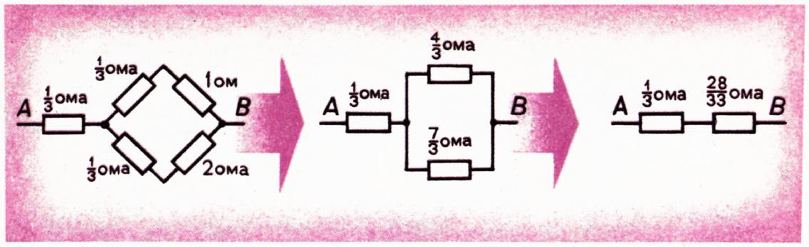
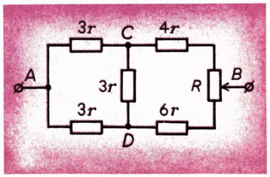
Fig. 4.
“triangle” ACD “star” as shown in Fig. 4.
Now it is clear that the resistance between points A and B will be equal to
We replaced the “triangle” ACD with a “star”, but it was possible to solve the problem differently - replacing the “star” ADB with a “triangle”.
Let now a battery with negligible small internal resistance and e.m. be connected to points A and B. With. E=1 in. We need to find the current through section CB.
The circuit must be transformed so that the resistance CB of interest to us is not affected. The transformation we did earlier (Fig. 4) will do.
Using that we get . After branching, the points are added in the ratio inverse to the resistances of the branches:
At the same time . (I is the current before the branching, is the current in the upper branch, is the current in the lower branch).
From here
It would be a little more difficult to find the current flowing through the CD section. To do this we would still have to find a current,
13
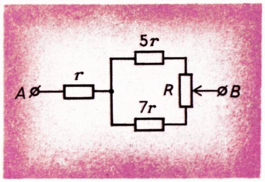
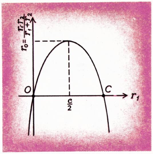
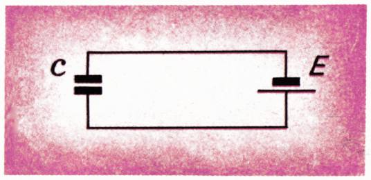
Fig. 6.
potentiometer. Moreover, the sum of resistance and remains constant. Let’s see what they should be so that the total resistance is maximum. We denote by and by . Then the total resistance of the parts of the circuit connected in parallel is . If we take into account that , then the resistance will be expressed as follows: . This expression is maximum when the number of slipels is maximum. But is the equation of a parabola (Fig. 7), the branches of which intersect the x-axis at points and . Therefore, the numerical fraction is greatest at . Since , this means that the resistance between points and is maximum if , that is , or .
It is clear that this is only possible if the resistance of the entire potentiometer is not less than . Otherwise, the maximum resistance between points and is achieved when the potentiometer slider is in its extreme position.
So the answer is: .
The method we have described is very convenient for sequentially transforming a complex diagram into a simple form. It allows you to calculate practically any complex target consisting of resistances.
This method can be applied to circuits containing more than just resistances.
Please note that we did not talk anywhere about physical processes in the circuit, but only used the formal expression for Ohm’s law: . It follows from it that when connected in series, their values are added, and when connected in parallel, the values reciprocal to resistance are added. It is clear that if any other physical quantities are related by a law similar to Ohm’s law, then all our conclusions are valid for them.
As an example, consider a circuit with a capacitor (Fig. 8). We know that , or .
14
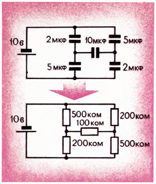
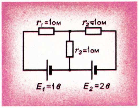
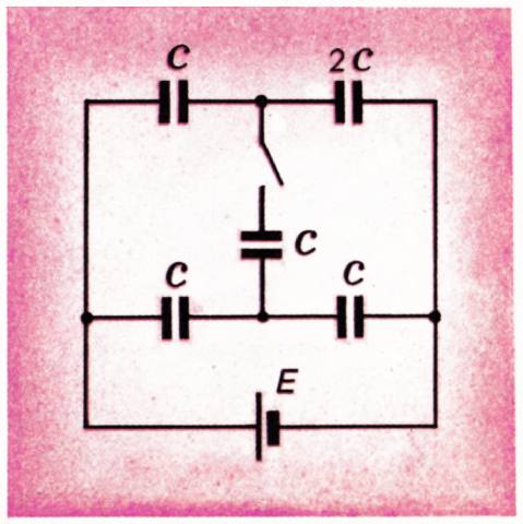
Fig. 9.
Let’s compare this with the expression for Ohm’s law .
It can be seen that the laws of positivity, only then together there is a charge, and together with resistance there are quantities, the inverse capacitance. This means that in order to find, say, charges on capacitors, you can do this. Instead of a circuit containing capacitors, draw a target containing resistances, and replace the capacitor with a capacitance of farads with a resistance . After we calculate the current in a circuit of resistances, we can immediately write what the charges are on the capacitors: if a current of amers flows through the resistance, then the corresponding capacitor will have a charge of coulombs.
E.m.f. The batteries remain unchanged during this transformation. But, of course, in a circuit with capacitors, the internal resistance of the batteries does not affect the result. Therefore, the goal changes, we will have to deprive the batteries of their internal resistances.
Let, for example, you need to find the charge on a capacitor with capacity (Fig. 9). To the capacitor