Rough automatic draft, low quality: expect mistakes and awkward wording. It will be replaced by a better translation. Original →
2
PARADOX OF S. I. VAVILOV
In geometric optics, the concept of a beam of parallel light rays having a finite cross section is often and fruitfully used. Moreover, even in the theory of such a wave phenomenon as integration, in many cases it is permissible to use this concept.
In many cases, but not in all. In the book “Microstructure of Light” by the famous Soviet physicist S.I. Vavilov, a very instructive optical paradox in this sense is analyzed.
Let us briefly recall what the energy of the integration picture looks like. Integration, as we know, is the addition of oscillations. In our case, the directions of the electric and magnetic fields fluctuate in the waves. These directions at each point in space at each moment of time determine the energy of the electromagnetic field. An electromagnetic wave transfers energy, and the concept of energy flux density can be introduced. This is what we call quantities equal to the amount of field energy flowing per unit time through a unit surface.
Each wave is also characterized by a phase. If, when adding two light beams, the difference in their phases remains the same all the time, we say that we are dealing with correct beams.
In the integration picture, resulting from the addition of two correct beams, a redistribution of light energy occurs. In the light stripes the energy is greater than the sum of the energies of the folded beams; in dark stripes, on the contrary, it is less. The excess energy in the light stripes is just compensated by its lack in the dark ones. The total energy, distributed over the entire integration picture, is exactly equal to the sum of the energies of the two integrating beams.
figure 1 shows the dependence of the energy flux density in the integration picture on the displacement across the screen on which it is observed. The picture was obtained by adding two correct light beams of equal energy. Horizon-
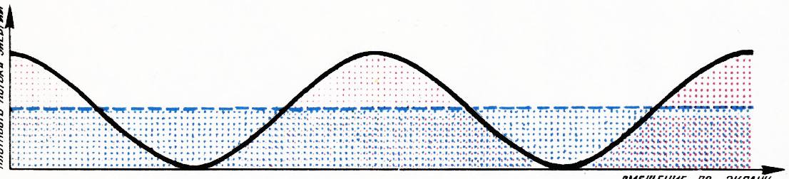
Fig. 1.
1 Quantum No. 2
2
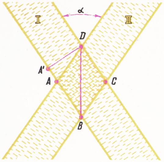
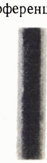
Fig. 2.
The tall dotted line depicts the sum of the energy flux densities at the added points. The parts of the curve going above this straight line correspond to light interference fringes, and the parts of the curve lying under the dotted line correspond to dark ones. The total energy distributed in the interference cartene is represented by the plane under the curve. This area is exactly equal to the area under the dotted line. The requirements of the strict accountant of nature - the law of conservation of energy - are strictly fulfilled.
Let us now move on to the paradox of S.I. Vavilov. Imagine two completely identical correct sharply limited light points of width , intersecting at a small angle . In the region interference will occur (Fig. 2).
To observe the interference pattern, you can install a screen perpendicular to the drawing plane, passing through points and . The interference pattern will consist of rectilinear alternating light and dark stripes filling the screen from point to point (Fig. 3).
The distribution of the energy flux density in the interference carten corresponds to the graph on figure 1. If the common beams have the same initial phases of light oscillations, then the difference in the phases of the light waves of the first and second beams at points lying on the straight line will be equal to zero. It thus corresponds to the middle of the central light stripe. In the middle of the adjacent, dark stripe, the phase difference should be equal to , in other words, the light vibrations in the common beams should be in antiphase. The phase difference is equal to the path difference of both waves to a given location, divided by the wavelength and multiplied by :
(1)
An increase in the length of the beam traversed by the wave by corresponds to a phase delay of . From formula (1) it follows that in the middle of the dark stripe closest to the center of the interference carten should be equal to .
Let’s calculate the path difference at point . A parallel beam can be considered as a flow of plane waves perpendicular to the directions of light rays.
Let us draw through the point (Fig. 2) one of the wave surfaces (surfaces of equal phase) of the first beam. The points and lie on this wave surface.
The paths taken by the bundles to the point are identical. In order to get to point , the wave surface of the first beam passing through point must
3
shift to the segment , and the wave surface of the second beam, which previously also passed through the point , must shift to the segment . As a result, a stroke difference will arise
(2)
It is clear that the same path difference, but with the opposite sign, will be at point . Let’s now start decreasing the angle . If is small enough, we can make equal to . Then all areas will be filled with one bright interference fringe. Consequently, the energy will exceed the sum of the energies of two intersecting beams. There is no compensation due to the formation of dark stripes, since they are absent altogether!
It is also possible to obtain, so to speak, a negative result by forcing beams with an initial phase difference equal to to intersect. Then the region will be filled with a dark interference fringe. In the first case, it is unclear where the additional energy comes from, in the second, it is unclear where the energy disappears.
Both cases clearly contradict the law of conservation of energy. Obviously, there is some defect in our reasoning that leads to the presence of one of the basic laws of nature. To understand what’s going on here, let’s write down formula (2) for the indicated case, when , and use the smallness of the angle ( for small ). We will show below that the angle is indeed very small. Then we get
(3)
or
(4)
Let’s take cm, cm, then radian. From (4) we see that problems with the law of conservation of energy arise when the angle between the beams is of the order of the relative wavelength to the cross section of the beam.
The solution to the paradox lies in the fact that at such small angles it is no longer possible to use the understandable ideal of a paradel beam of a finite cross-section.
Any attempt to implement such bundles will fail. By limiting the size of the beam, the phenomenon of diffraction necessarily leads to its transformation into a divergent beam. The beam divergence angle is determined precisely by formula (4). In this case, naturally, the angle at which the beams intersect can be determined only with an accuracy of the order of the divergence angle of the intersecting beams.
If diffraction had not yet been discovered, we, on the basis of the law of conservation of energy and formula (4), should not only agree on its existence, but also point out the basic pattern governing the magnitude of the diffraction angle. This is a good example of how the conservation law in physics can always serve as a reliable guiding star.
Taking light beams, we will never, of course, get a contradiction with the law of conservation of energy. In interference experiments of this type, it should always be reduced to the spatial redistribution of the energy flow.
There are, however, interference experiments where even more subtle energy paradoxes will arise, but that, as they say, is another story.