Rough automatic draft, low quality: expect mistakes and awkward wording. It will be replaced by a better translation. Original →
54
- Equivalent node method
The idea behind the method is to treat different nodes of a circuit that have equal potential as one node. In this case, the potential in the resulting “glued” node is equal to the total potential of the original nodes.
If equivalent nodes are connected by a conductor (without resistance), then the electrical condition in all nodes and branches of the circuit does not change, since no current will flow through this conductor.
Let’s look at examples.
Task 1. Find the resistance equivalent to the section of the circuit shown in figure 1, (all resistances in the diagram are the same and equal to ).
Solution. It is easy to understand that nodes 1, 2 and 3 have equal potential. In fact, from the symmetry messages it is clear that the currents flowing through branches A-1, A-2 and A-3 are the same. Therefore, due to the equality of the resistance of these branches, the potential drops on them are also the same and the potentials of nodes 1, 2 and 3 are the same.
Similarly, it can be shown that nodes 4, 5 and 6 also have equal potentials (equivalent).
It is clear that the circuit resistance will not change if equivalent nodes 1, 2 and 3 are connected together. The resistance of the circuit will not change if you connect the second three equivalent nodes.
Having done this, we obtain a circuit equivalent to this one (Fig. 1, 6). The resistance of this circuit is not difficult to find: the resistance of section is , the resistance of section is , and the resistance of section is . Therefore .
56
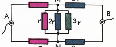
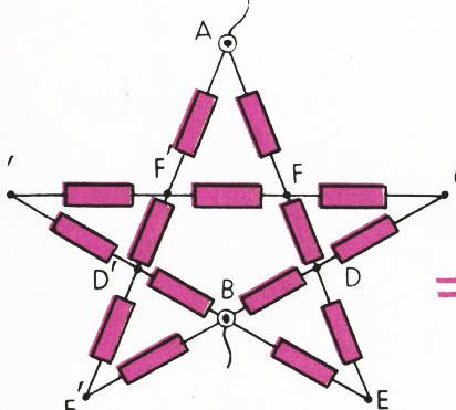
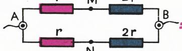
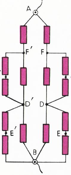
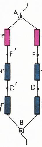
Fig. 3.
Actually, no current flows through section . Pozny can remove section and we get the equivalent circuit shown in figure 4, b. After simple transformations of the circuit (Fig. 4, θ) it is easy to calculate that its resistance is .
- Method of “reproduction” of nodes
This method is also closely related to the method of equivalent nodes. If replacing several equivalent nodes with one (connecting nodes) led to an equivalent circuit, then the reverse replacement of one node with several equivalent nodes will not violate the electrical conditions in the rest of the circuit.
Let us give examples of circuits for which such a transformation is appropriate.
Task 5. Find the resistance of the circuit section shown in figure 5, a.
Let’s replace node with tray nodes; , and (Fig. 5, b). However, we still need to prove that these circuits are equivalent. For circuit equivalence, nodes , and must be equivalent. But this is very indo, since the potential difference - is equal to half the potential difference of points and : .
Similarly, from the symmetry reports of the inclusion of resistance, it is not difficult to find that and . Therefore, , that is, nodes , and are equivalent. Now finding the circuit resistance is not difficult. It is equal to 0.8 (Fig. 5, θ).
58
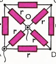
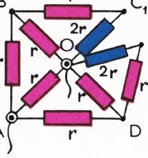
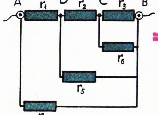
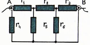
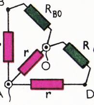
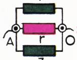
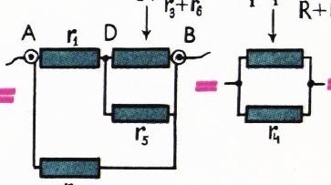
Fig. 7.
Task 7. Find the resistance of the circuit shown in figure 7, a.
Solution. Let us replace branch with two parallel branches with equal resistances . We then divide node into equivalent nodes and (their equivalence follows from the symmetric relative messages of nodes and ). The circuit shown at figure 7, 6 is equivalent to the circuit at figure 7, a. Let’s find its resistance. Sections and are connected in parallel. Postural resistance .
Likewise, . Now nodes and are connected by three parallel branches with resistances . The total resistance of the circuit is (Fig. 7, g).
- Recurrent method
Recurrent methods for solving problems are general methods in which the problem is solved step by step, and at the th step it is necessary to use the results obtained in the previous steps. Recurrent methods in problems of calculating circuit resistance are especially convenient when the circuit has a repeating structure and the number of resistances is large.
Task 8. Find the resistance of the circuit shown in figure 8, a, where .
Solution. Let us redraw the chain as shown in figure 8, 6. It is clear that the calculation must be carried out from the end . Replacing resistance and with the equivalent resistance , we obtain the circuit shown in figure 8, c. Now the resistances and can again be replaced by the equivalent (Fig. 8, g). The total resistance of the circuit is